
Trailer Wiring Schematic 7 Way Free Wiring Diagram
On a Manual adjusted brake assembly (shown to the right) it will be a curved spring below the adjuster. Due to the way that these brakes operate we absolutely recommend being consistent through the trailer. It is NOT SAFE to run both types of brakes on the same axle.
trailer wiring diagram electric brakes Wiring trailer diagram brake
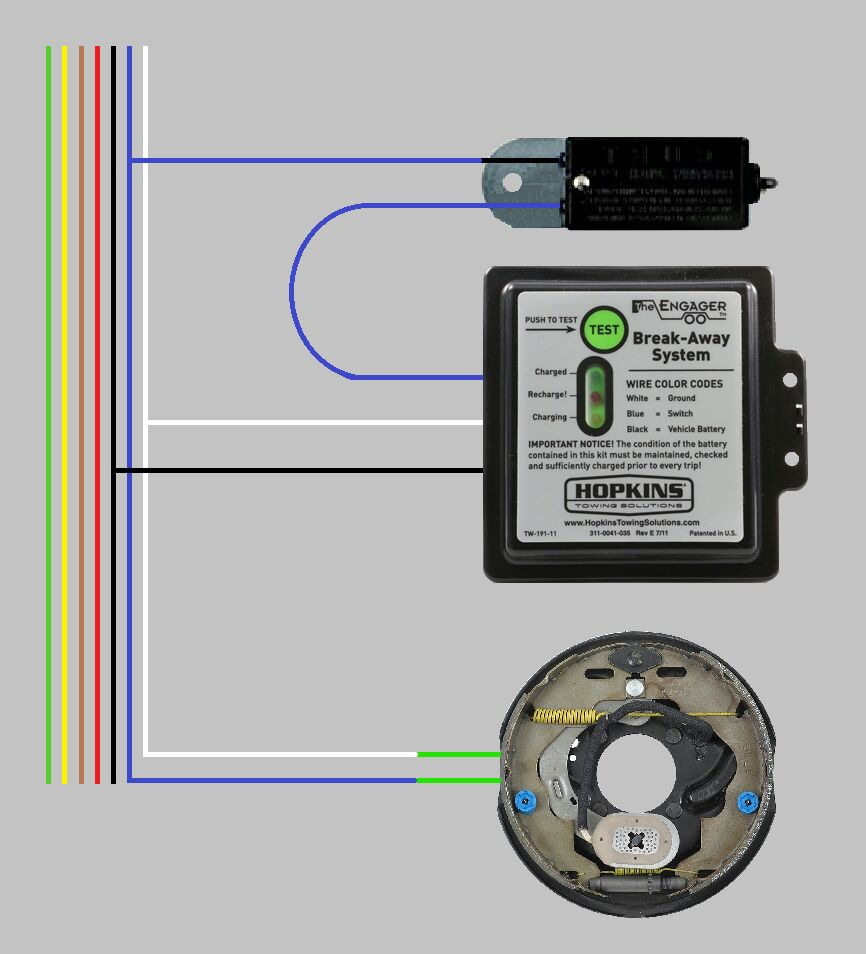
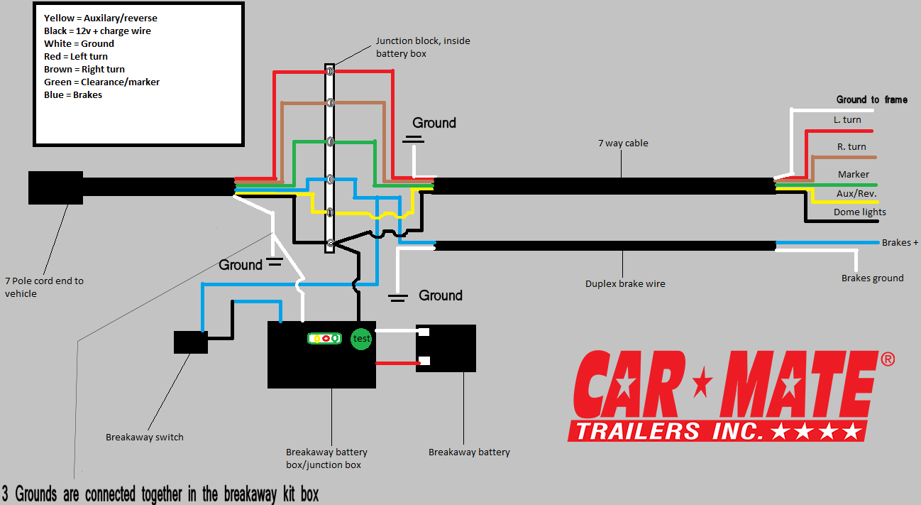
The concept of the "Breakaway" is to automatically apply brakes if a trailer comes disconnected from the tow vehicle. We've seen how terrible this is - and even more terrible - it's not that uncommon for a trailer to unhook. People forget to tighten the hitch, or don't get it on totally. Either way, that's where the trailer Breakaway Kit comes in.

Electric Trailer Brake Wiring Schematic Free Wiring Diagram
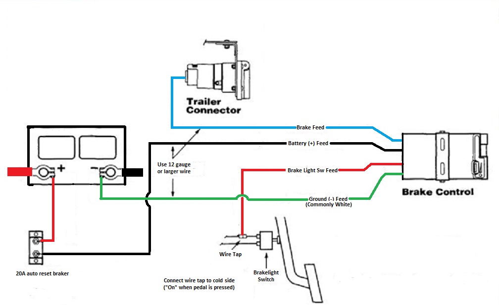
Want a brake controller with no installation? Check out Echo™ How to install a trailer brake controller video Brake Control Install: CURT 51120 Discovery Brake Control Watch on Step 1: Disconnect the negative battery cable Any time you work on your vehicle's electrical systems, it is a good idea to disconnect the battery.

Unique Wiring Diagram for Car Trailer with Electric Brakes diagram
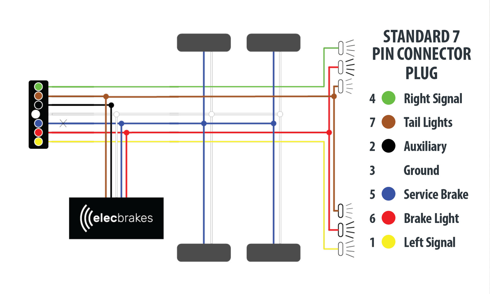
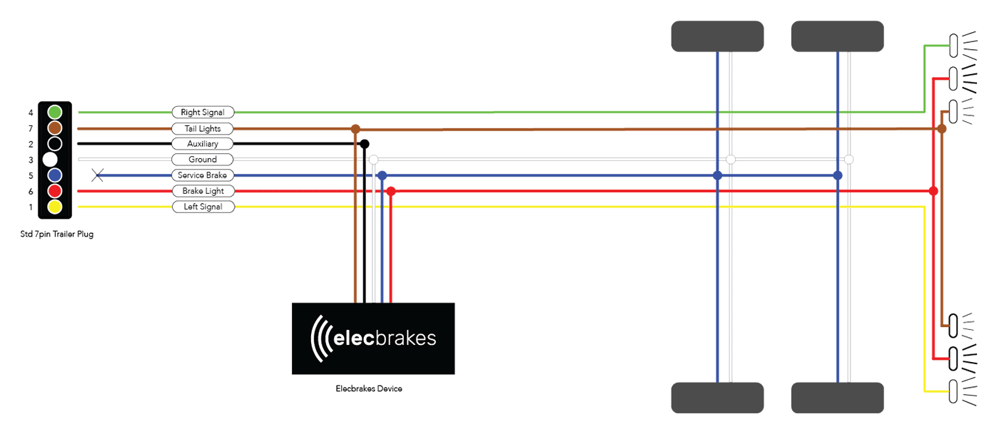
RV Standard Green: Tail/running lights Yellow: Reverse Lights Brown: Right turn/brake light White: Ground wire Blue: Brake controller output Black: Battery hot lead Red: Left turn/brake light Not sure exactly what each wire does? The easiest way to figure it out is to use a circuit tester to confirm the function of each wire.

Trailer Brake Wiring
A 7 way trailer wiring diagram with brakes is essentially a schematic drawing of the wiring system for the trailer and its brakes. It shows the components of the trailer and their positions relative to one another. This diagram can be used to troubleshoot wiring issues and make repairs or modifications to the wiring system.

Trailer Brake Wiring Diagram With Brakes Database
Typically the 5-Way Flat is used for trailers with surge brakes or hydraulic brakes. The additional wire is tapped into the backup lights to disengage the hydraulic trailer coupler (actuator) when the vehicle is reversing, thus turning off the trailer's brakes. 5-Way Flat Trailer Connector 5-Way Flat Vehicle Connector 5-Way Round Trailer Connector
98 Durango Brake Switch Wiring Harnes Wiring Diagram Networks
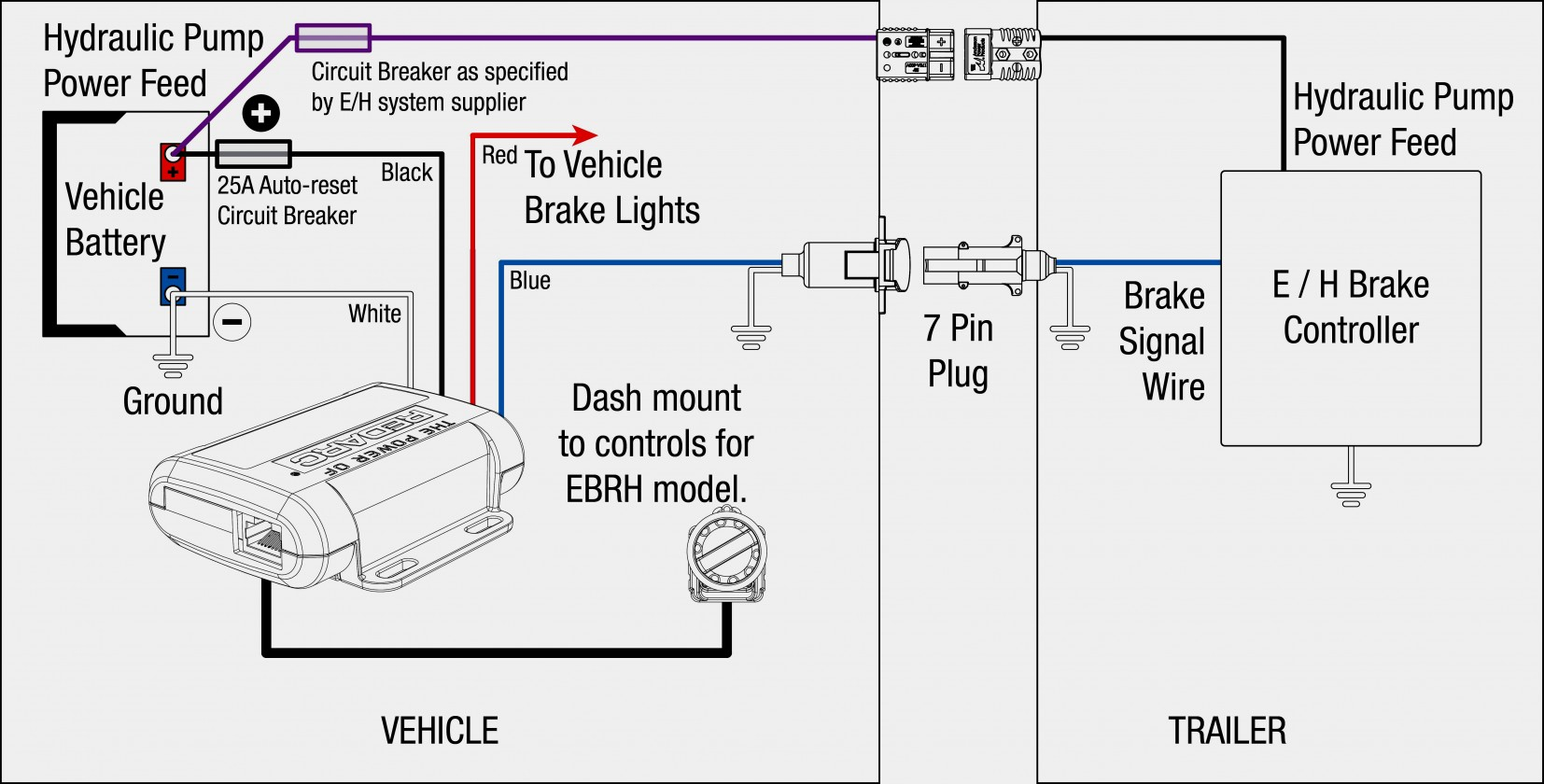
Table of Contents How to wire trailer brakes? Trailer brakes are wired 7 ways. On the vehicle side, the blue wire connects to the brake controller The blue wire connects to the brake controller on the electric brakes Use 14 gauge wire for single axle trailers and 12 gauge wire for tandem trailers. How to wire a third brake light on a trailer?

Curt Brake Controller Wiring Diagram Free Wiring Diagram
I go over all the basics on wiring up your vehicle trailer harness and electric brakes.
Electric Trailer Brake Wiring Schematic Fannie Top
Any vehicle towing a trailer requires a trailer wiring harness to safely connect the taillights, turn signals, brake lights and other necessary electrical systems. If your vehicle is not equipped with working trailer wiring, there are a number of different solutions to provide the perfect fit for your specific vehicle.
Trailer Brake Wiring Diagram Cadician's Blog
Various connectors are available from four to seven pins that allow for the transfer of power for the lighting as well as auxiliary functions such as an electric trailer brake controller, backup lights, or a 12V power supply for a winch or interior trailer lights.

Jayco Wiring Diagrams Wiring Draw
Typically, a utility trailer wiring diagram will include the following components: a power source, a brake controller, a brake switch, brake lights, turn signals, and ground connections. The power source is usually the vehicle's battery, which provides the necessary electrical energy for the trailer's braking system.
Electric Brake Wiring Grounding Out
The colors for a 4-pin trailer wiring diagram are: White: Ground wire. Brown: Tail/running lights. Yellow: Left turn/brake light. Green: Right turn/brake light. 18-gauge wire is the minimum recommended size for the 4-way plug. This should be used for the lights.

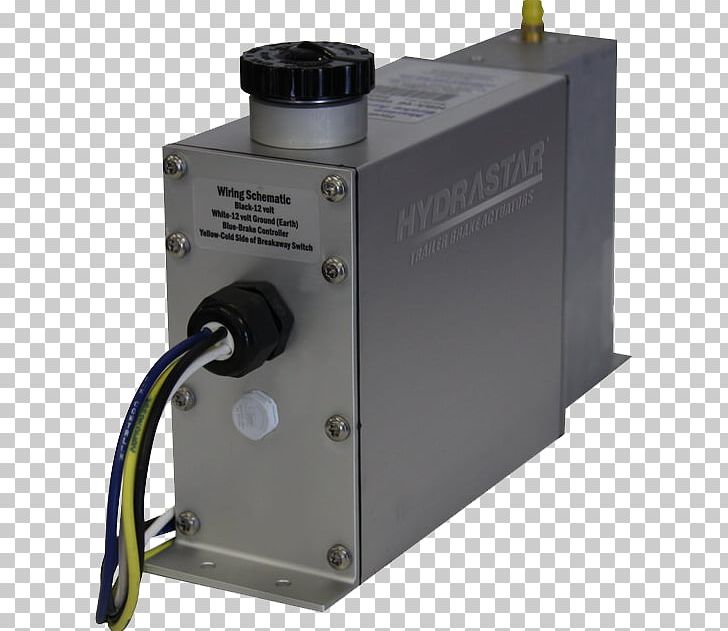
Wiring Diagram For Trailer Brake Battery Box For A Kyra Wireworks
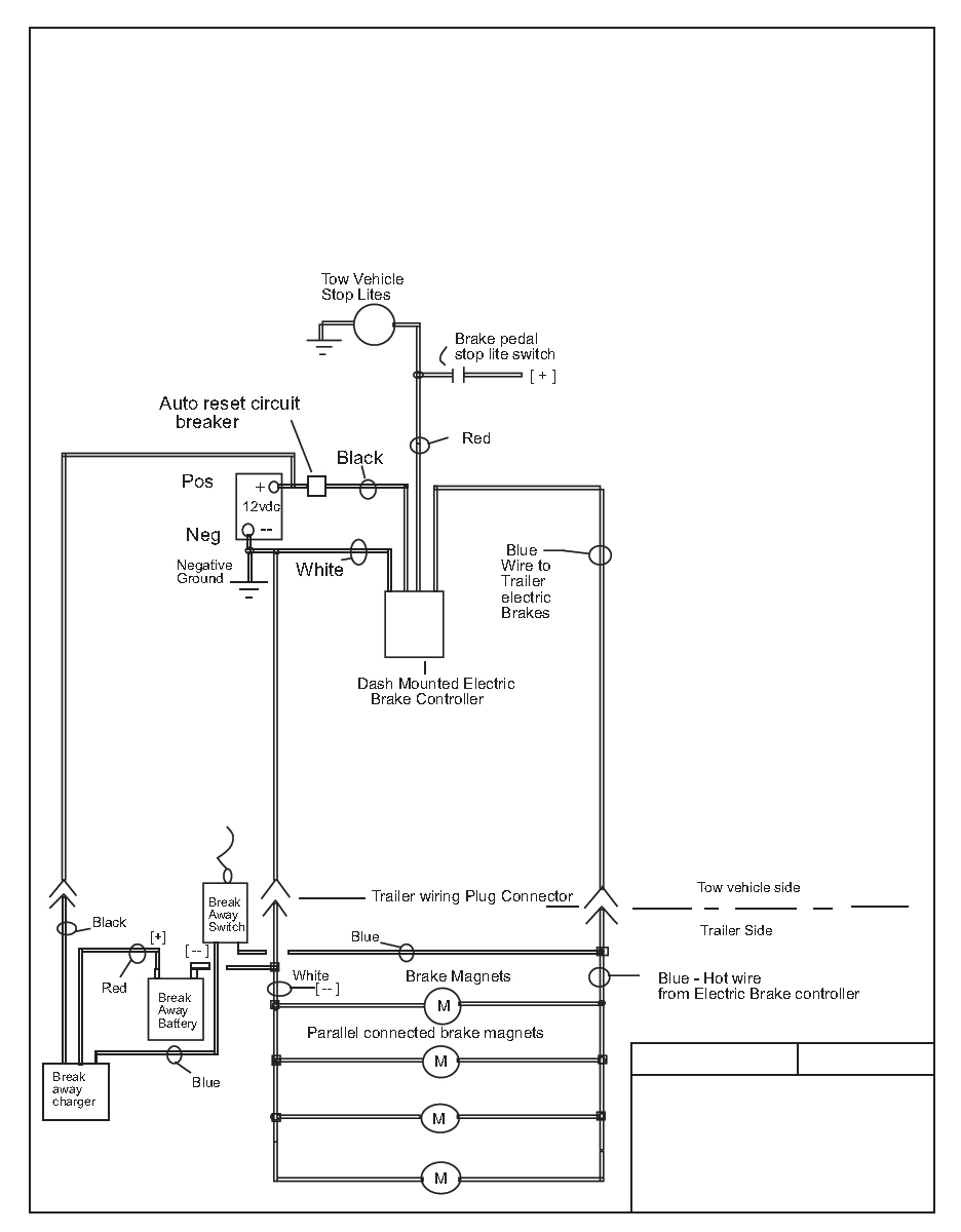
If the trailer wiring is running down the left side of the trailer, then we splice the left side brake assemblies into the main electric brake power wire coming from the 7-way connector. We then run a jumper wire from the electric brake power wire to the right side brake assemblies (see photo).
Trailer Brake Wiring Diagram Wiring Diagram
A wiring diagram for trailer with electric brakes is composed of several components. These components include the wiring harness, fuses, and circuit breakers. The wiring harness connects all the components together and is secured with zip ties or other methods of fastening. Fuses are designed to protect the wiring from being overloaded.
Electric Trailer Brake Wiring With Breakaway
The four wires control the turn signals, brake lights and taillights or running lights. They also provide a wire for a ground connection. 4-way trailer connectors are available in two styles: flat and round. They have the same electrical functions, but they do have a few differences. 4-Way Round Pin Connector
Brake Controller Wiring Schematic
Click for more info and reviews of this Dexter Trailer Brakes:https://www.etrailer.com/Accessories-and-Parts/Dexter/23-26.htmlCheck out some similar Trailer.